In November
2010 I have been started with the construction of my first SDR Tansceiver.
The transceiver is based on the Transceiver published in the German Funkamateur
Magazine.(Funkamateur)
Design goals for my SDR transceiver:
Service friendly
Enough space for future modifications
Easy to be modfied
Modular construction
Built in Power Supply (no switch mode)
Modern 100 Watt Mosfet PA with professional
Mosfets
Built into a homebrew 19 " enclosure
Automatic Band Switching
Dedicated computer only be used for the
transceiver
Should base on a Mini ITX running on at
least 3 GHz and I-Core processor
Computer should be built in to a separated
enclosure in the same style of the transceiver to over come noise problems
Computer should has a same style enclosure
as the transceiver
Computer should have built in power supply
for 230 V and able to run on 12 V- 24 DC as well
4 GB of memory to be in the future to 8 GB
for running under windows 7.0
minimum of 12 x USB Buses
at least one standard Serial bus
Im November 2010 sind wir angefangen
mit der bau einem SDR Transceiver, Das Konzept is basiert auf die Transceiver
veröffentlicht in Funkamateur. Mein version wird in ein eigenbau 19 Zoll Gehause
eingebaut zusammen mit 25 A 13.8 V DC Netzteil, Moderne 100 Watt Mosfet Endstufe mit
automatischer Bandwahl. |
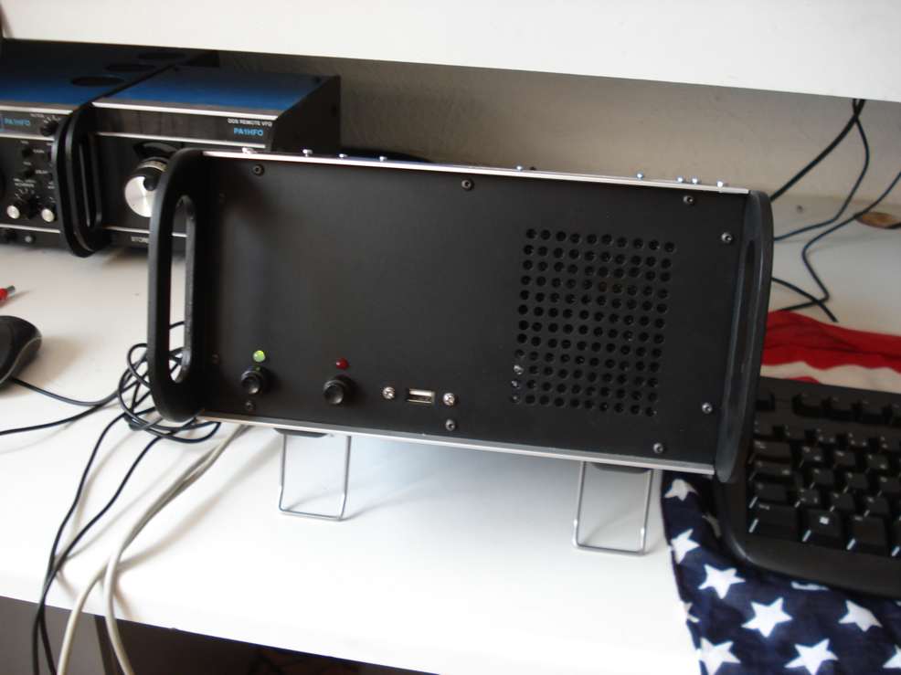
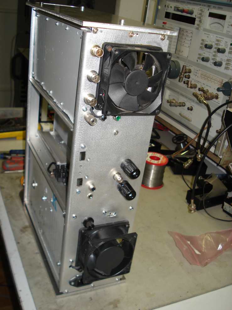
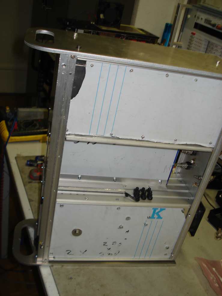
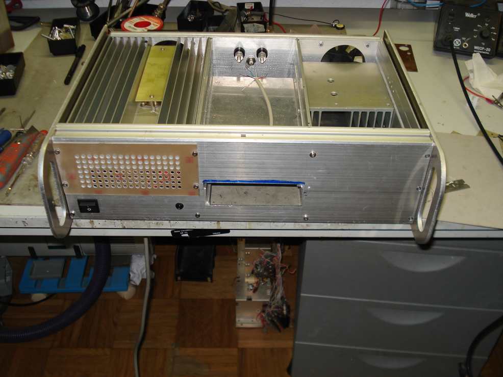
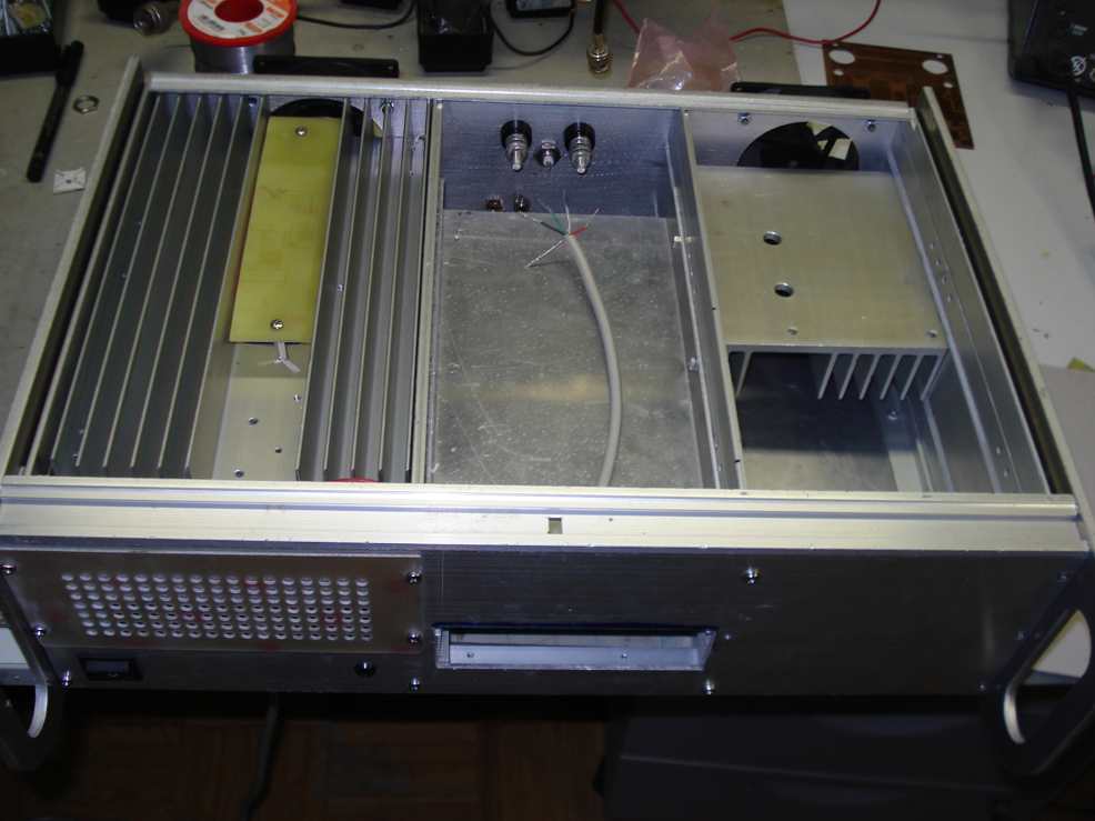
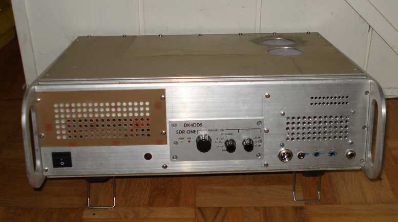
| Pictures
of the the 19 " enclosure under construction |
|
 |
|
|
|
|
|
|
|
Circuit
Diagram 20A Power Supply Schaltbild Netzteil 20Amp |
|

|
|
Down Load Circuit Diagram
Schaltbild herunterladen |
|
|
|
|
|

|
|
|
|
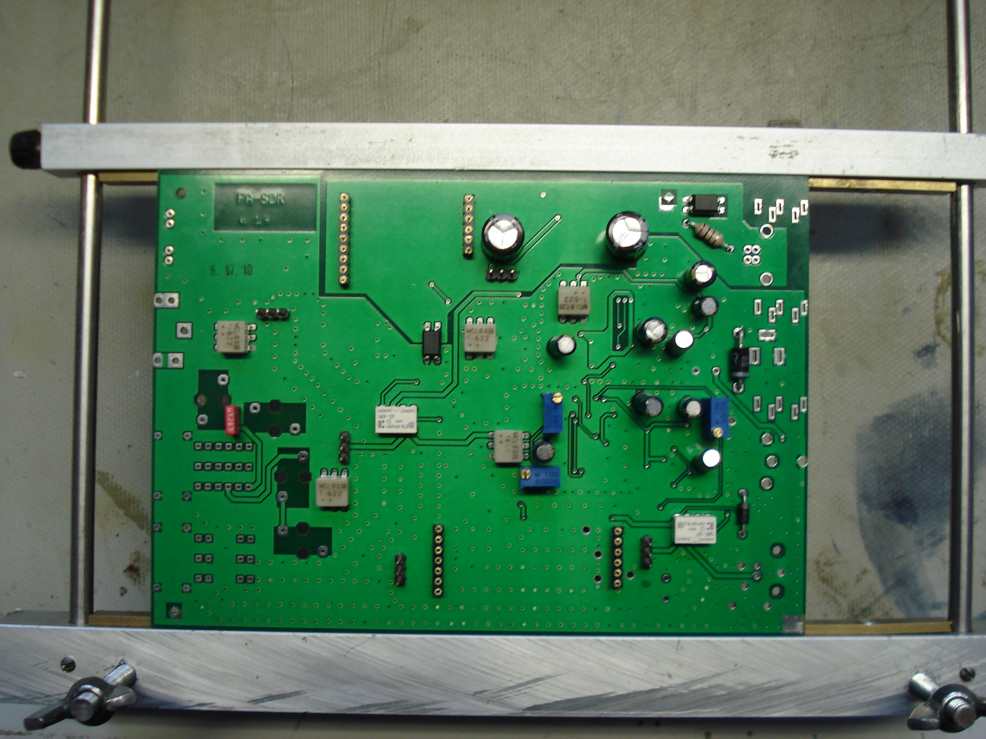
| The FA SDR transceiver board is
placed in the DK4DDS assembly fixture and the through hole components are place on to the
board. |
| Die FA SDR
Leiterplatte ist in der DK4DDS Bestückungsadaptor plaziert und die Durchsteck-Bauteilen
werden bestückt. |
|
|
|

|
|
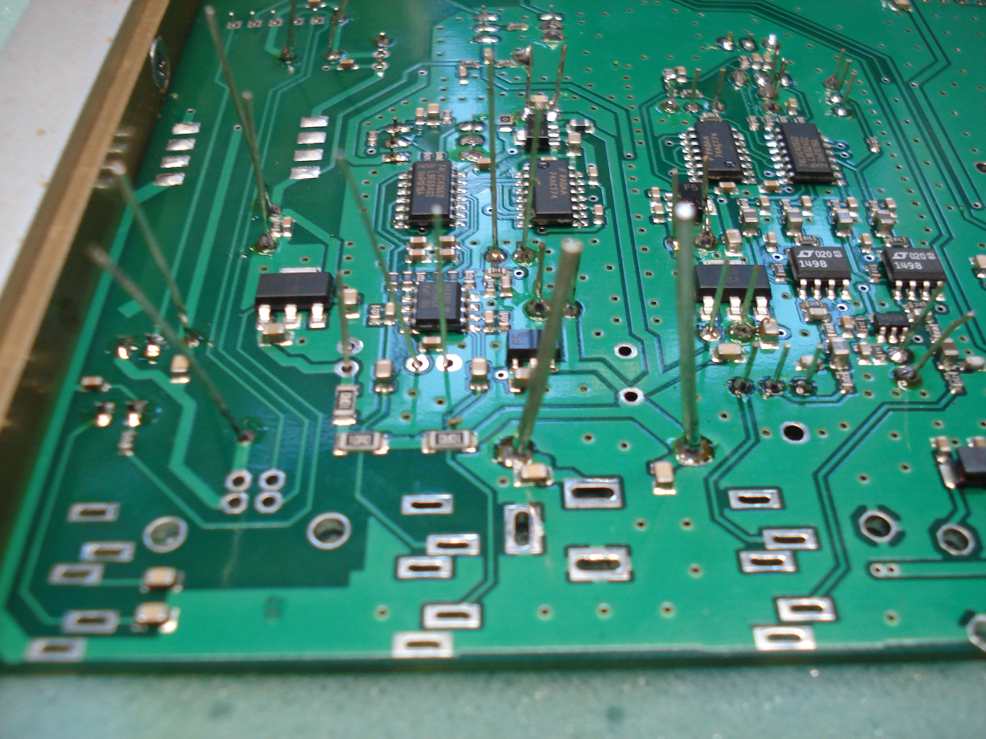
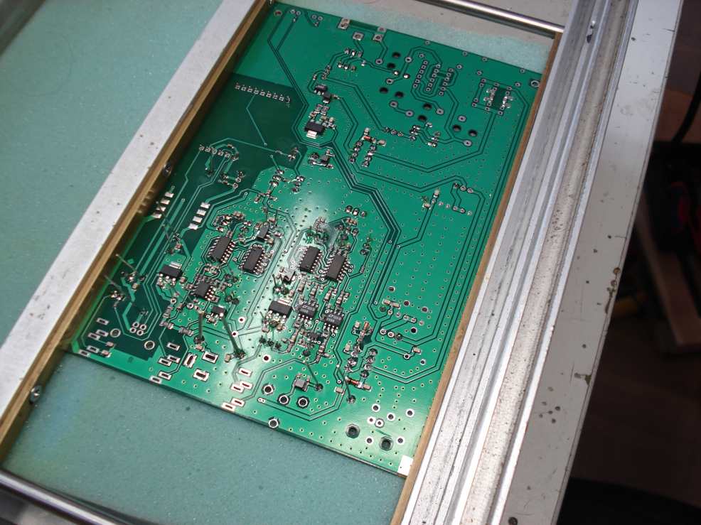
The through hole components are
soderded and cutted at the soldering side (bottom)of the pcb.
Das Löten und Schneiden von die Durchsteck-Bauteilen. |
|
|
|
|
|
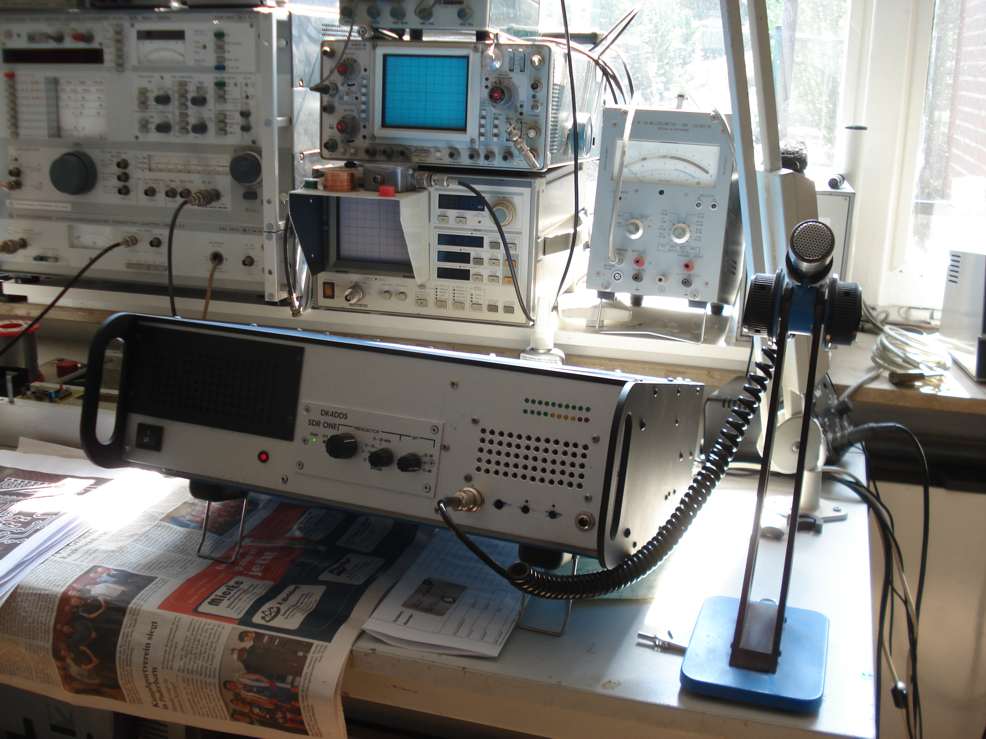
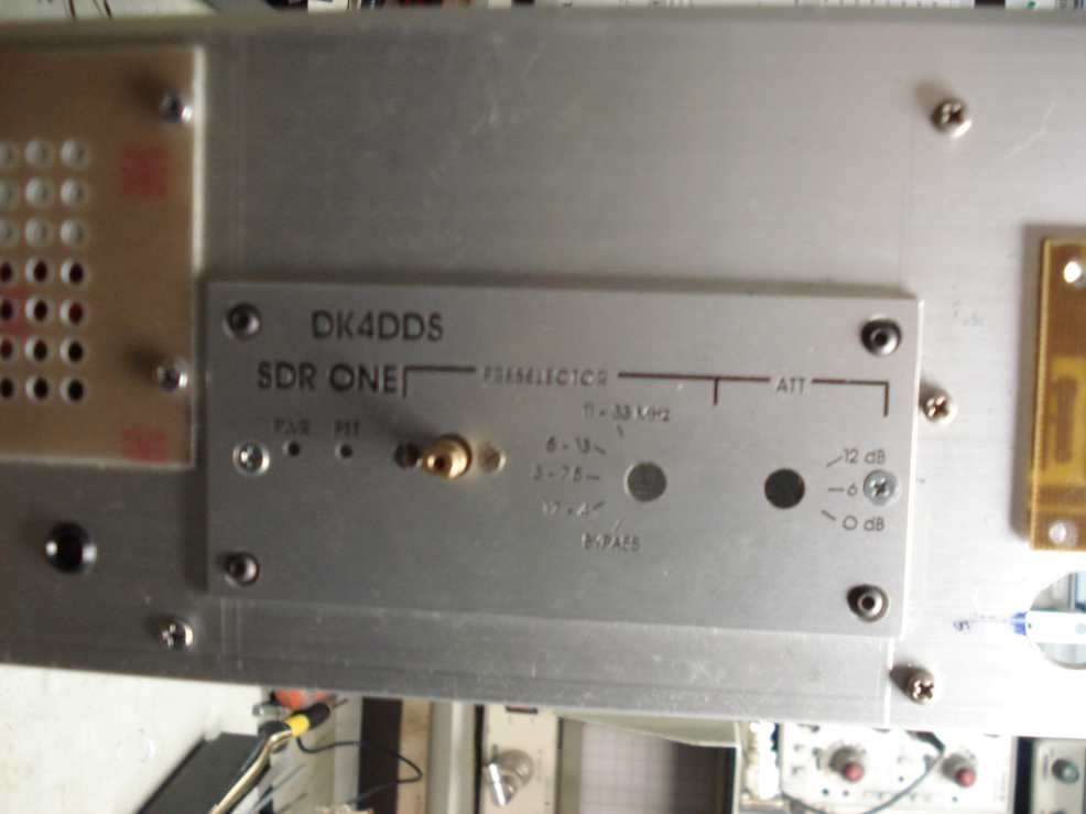
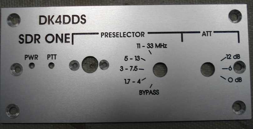
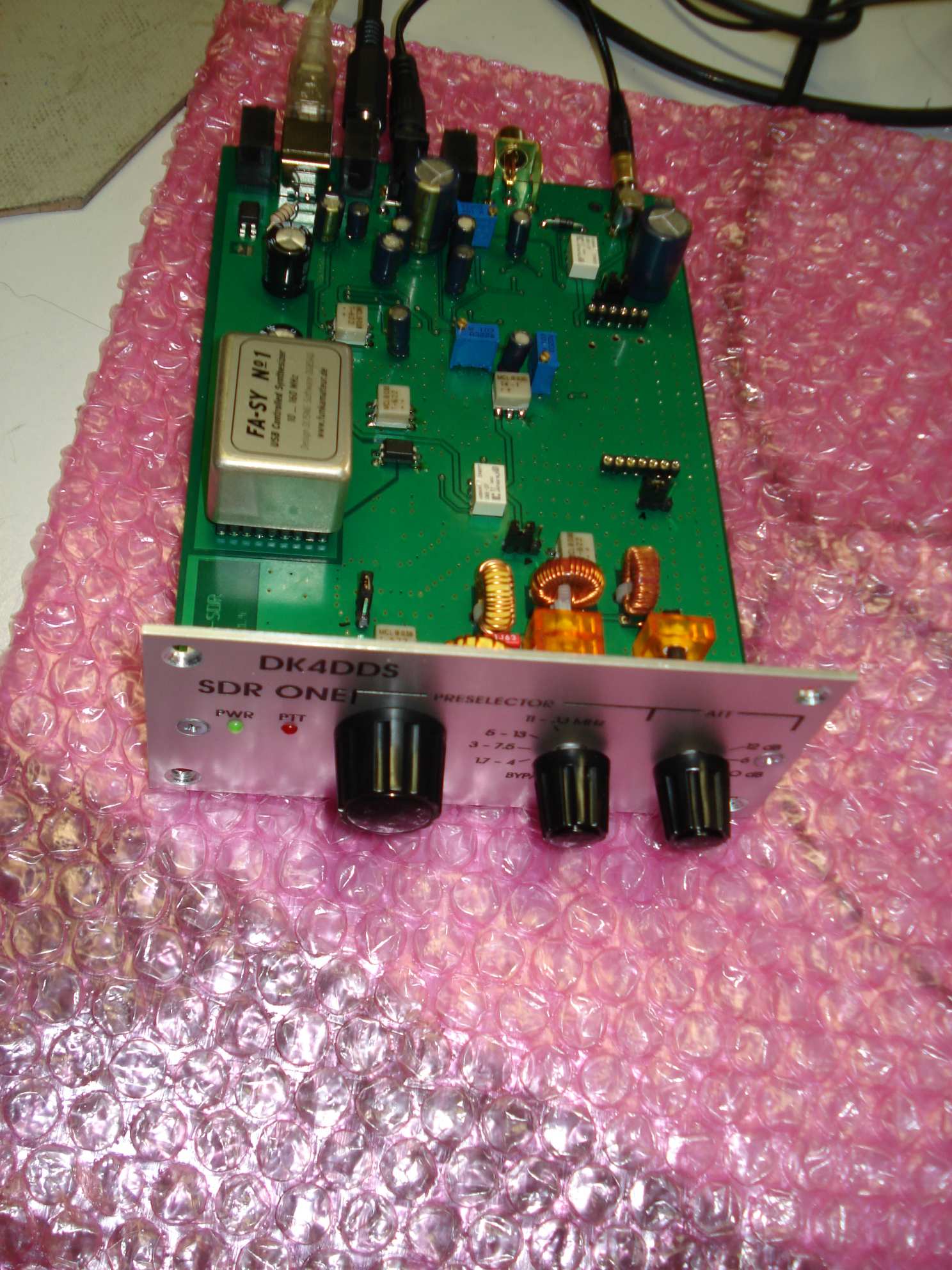
| DK4DDS Front for
the FA SDR Transceiver Module(FA SDR PCB) |
|
|
|
|
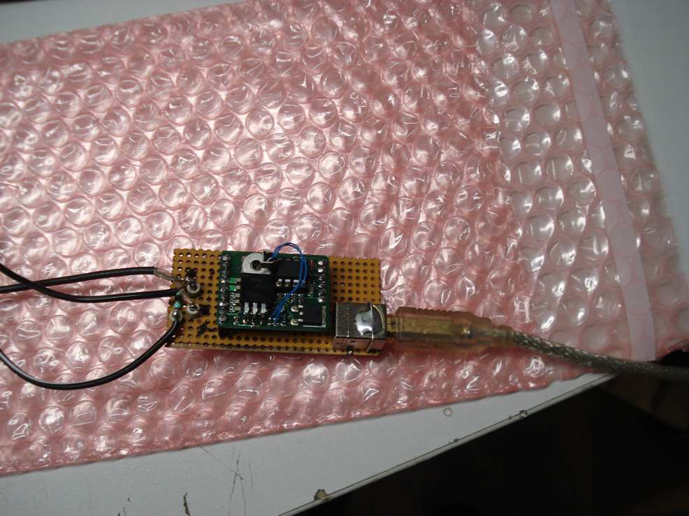
Synthesizer
under test & Calibration (Placed in Test Fixture) |
|
|
|
|
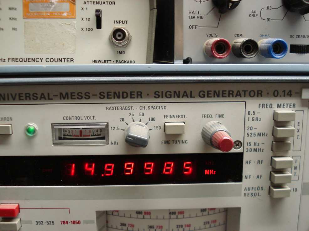
| Calibration with
accurate Frequncy Counter |
|
 |
|
|
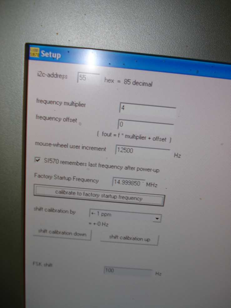
| Set Up Software for
calibrating the Synthesizer |
|
|
|
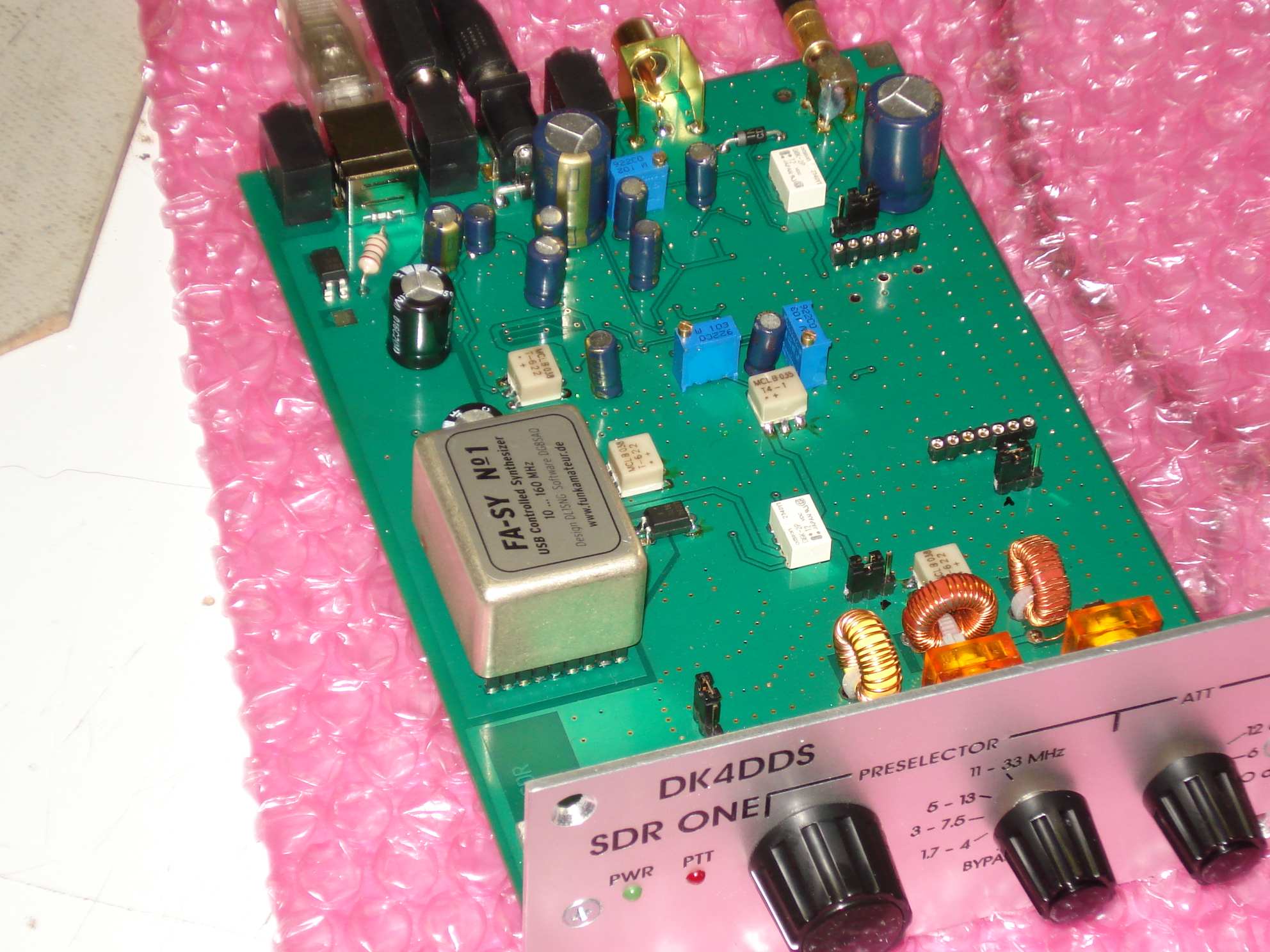
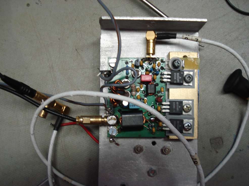
| FA SDR TRX
PCB under Test |
|
|
|
|
|
|
|
|
|

|
|
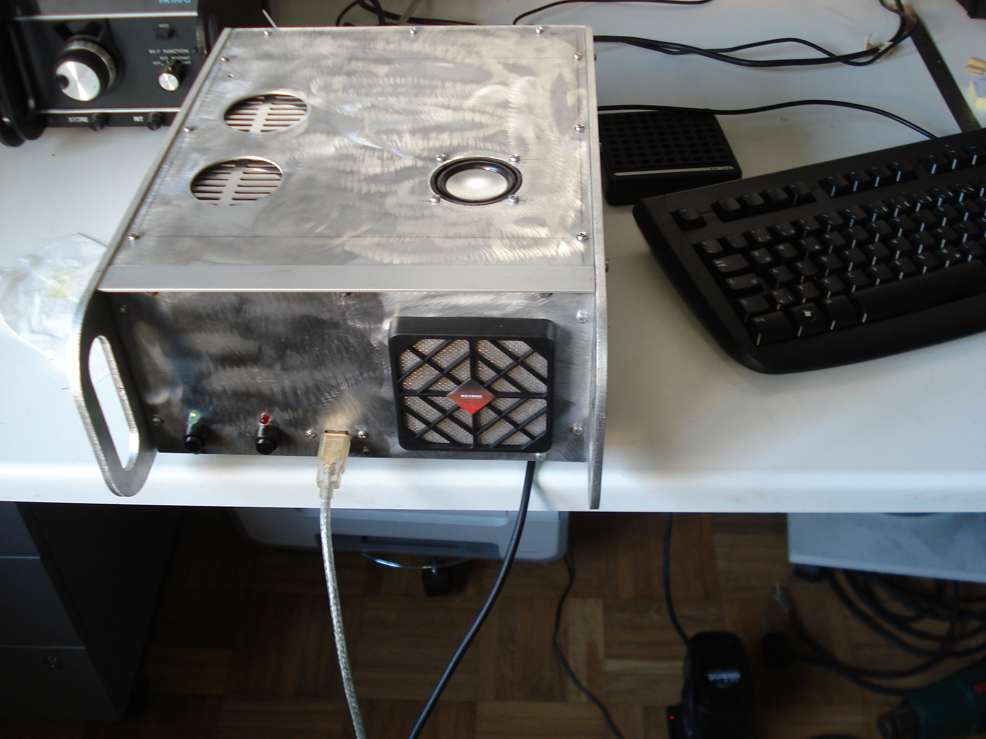
| My dedicated SDR
ONE Computer |
| Mini ITX DH57JG Board with 3. Ghz Intel I3 Core 540 Processor 12 X
USB, 4 GB Memory, Running under Windows XP, 450 GB Hard Disk. The baord has an integrated
soundcard with sampling rates of 48000, 96000 and 19200 Khz, Built in Power Supply 230 V
AC and also capable to run from 12- 24 DC sources. |
|
|
 |
|
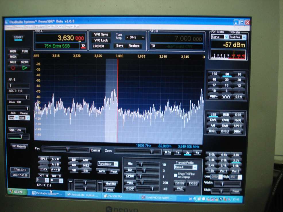
The receiver
section is runnng now FB |
|
|
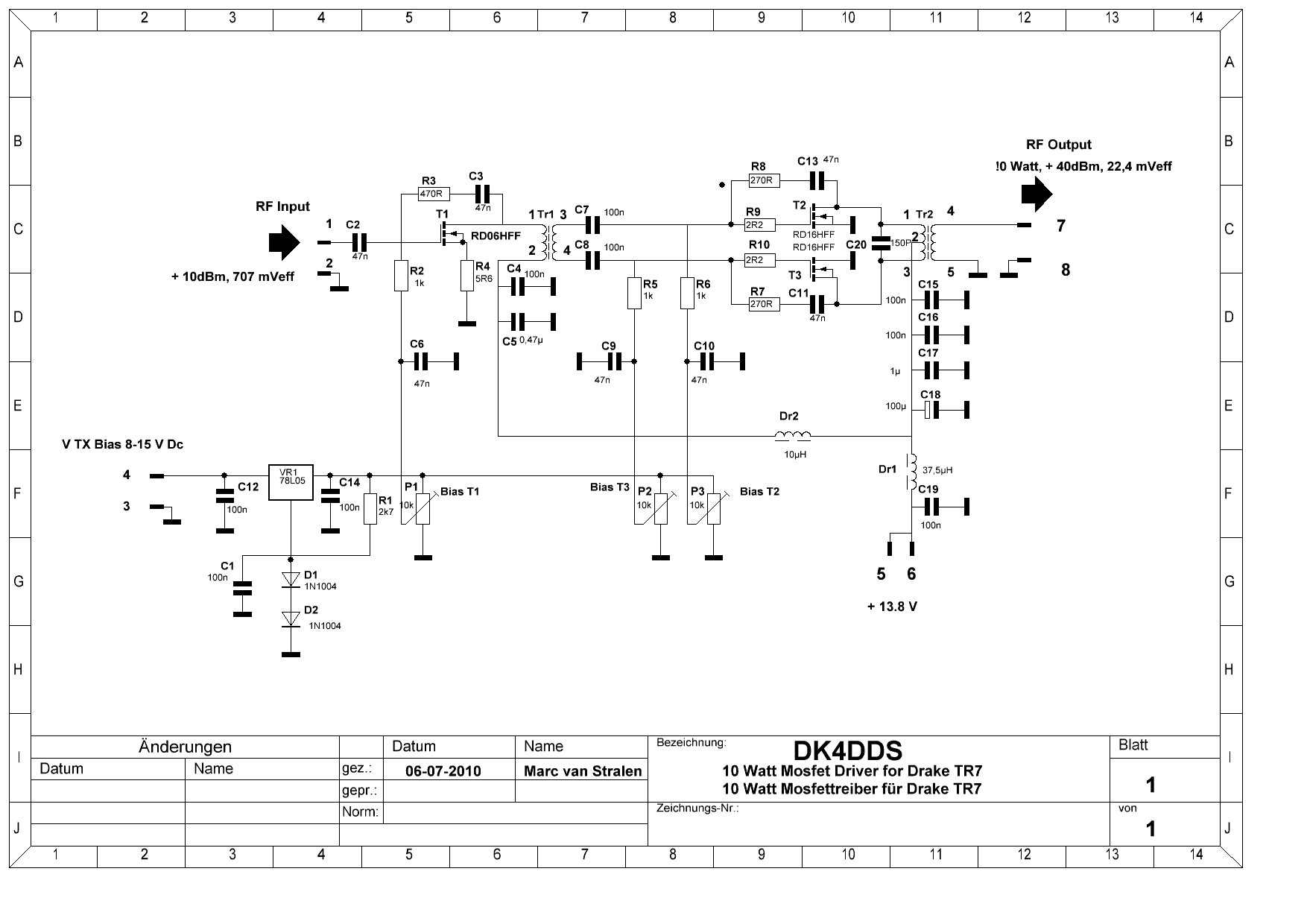
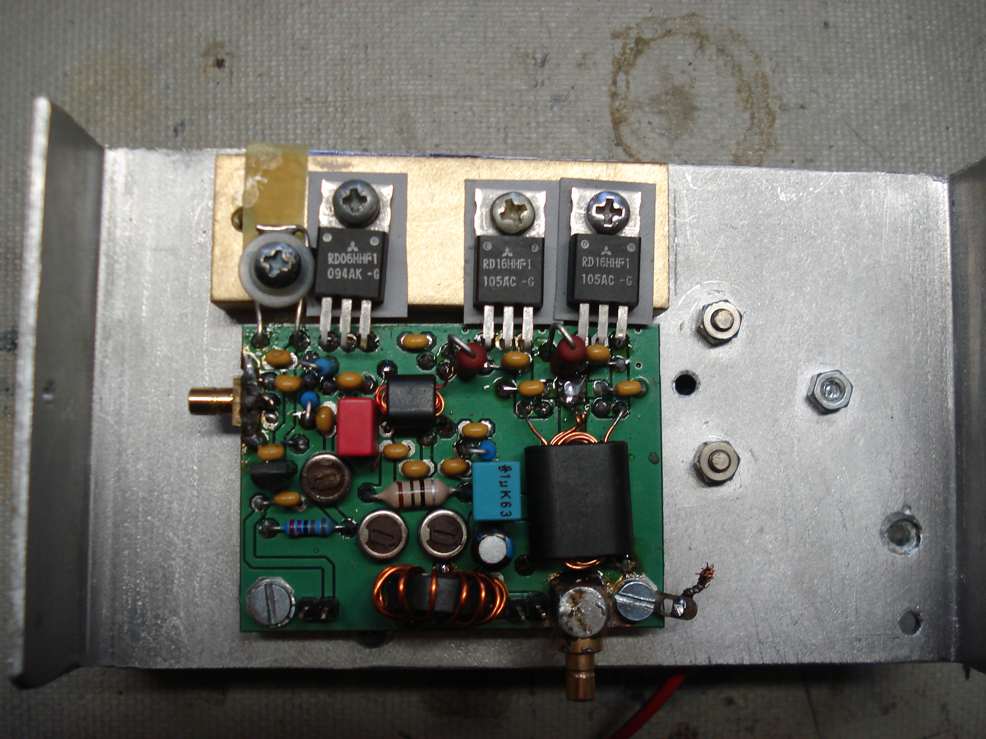
Circuit
Diagram10 Watt Mosfet Driver for 100 Watt Mosfet PA |
|
10 Watt Mosfet
Treiber für 100 Watt Mosfet Endstufe |
|
Down Load:
Circuit Diagram 10 Watt
Driver Schaltbild 10 Watt Driver in PDF Format |
This PA is availbe as a kit by QRP PROJECT in Berlin
Germany www.qrpproject.de
|
|
 |
|
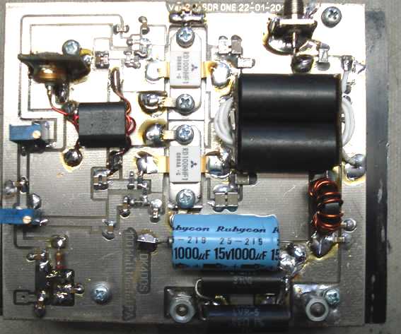
100 Watt Mosfet PA for TR 7
|
Circuit Diagram
100 Watt Mosfet PA |

|
|
Schaltbild 100
Watt Mosfet Endstufe |
|
Down Load Circuit
Diagarm in PDF Format /Herunterladen Sie das Schaltbild 100 Watt Endstufe in PDF |
|
|
|

|
|
| Do you need your proto type PCB's ( double and single sided) at very
competive prices prices ?
Have a look at the right place!
Visit: www.platinenbelichter.de
or sent an E-mail to info@platinenbelichter.de
Sie brauchen müster entweder
einzel Platinen ?
Einseitig beschichtet entweder Doppleseitig beschichtetfür super
gunstige Preisen !
besuchen Sie www.platinenbelichter.de
oder senden Sie ein E-mail an info@platinenbelichter.de |
|
|
|
|
Down
Load Construction Details of Transformer T2 |
|
|
Down Load Viewer Sprint Layout 5.0
to print and view the PCB Lay Outs |
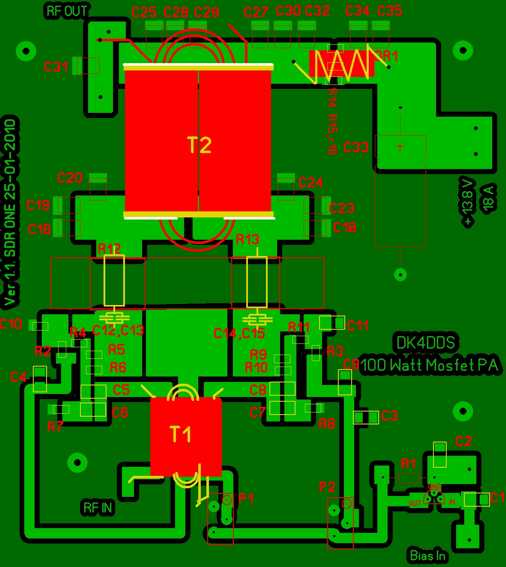
Down Load the 100 Watt
Mosfet Sprint Layout PCB File |
Down Load the Bill of
Materials of the 100 Watt Mosfet PA |
|
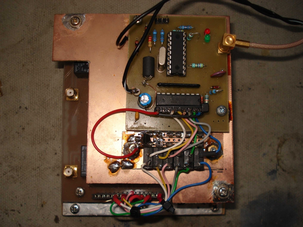
| Automatic
Band Decoder for Switching the Low Pass filters of the 100 Watt
Mosfet PA |
|
| If have first tested my
Mosfet PA and Low Pass Filters by switching the relays of the Low Pass filters manually
due the fact it is not able to this direct with the Power SDR Software and
my hardware. So have made this small PIC controller to over come this
problem. The PIC controller will measure very fast the RFoutput frequency of the PA
and selects the right low pass filters. This concept you will find also in external
transistor and Mosfet Amplifiers. If
you want to receive the software for the PIC mail me dk4dds@t-online.de |
 |
|
Download the Circuit Diagram in
PDF format
Down Load the Circuit
Diagram in S-Plan 7.0 format
Herunterladen Sie das
Schaltbild in PDF Format
Herunterladen Sie das
Schaltbild in S-plan 7.0 |
| Automatic
Band Decoder Mounted on to the Low Pass Filter Unit |
 |
|
 |
|
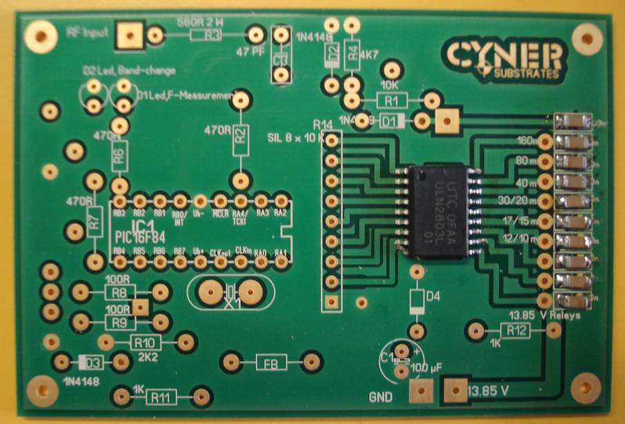
We are offering from stock the professional gold
plated pcb´s for the Automatic Band Decoder
Dimensions 52 x 77 mm |
| Price € 12 Payment via Pay Pal includes Postages and Packing |
 |
|
| Gold
Plated Double Sided PCB Automatic Band Decoder Component Side |
|
 |
|
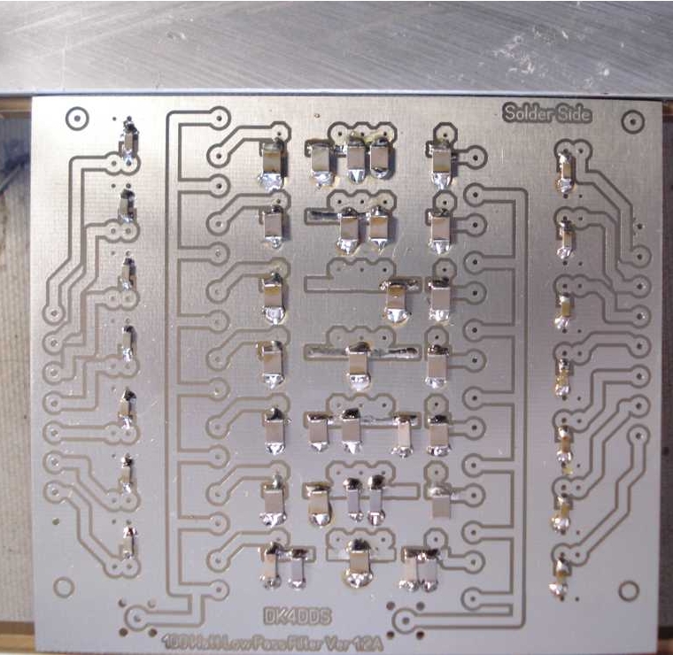
| Gold
Plated Double Sided PCB Solder Side |
|
Down Load the PCB
Lay Out File in PDF format
Down Load
the PCB Lay Out File in Sprint 5.0 format
Laden Sie das
Layout in PDF herunter
Laden Sie
das Layout in Sprintformat herunter |
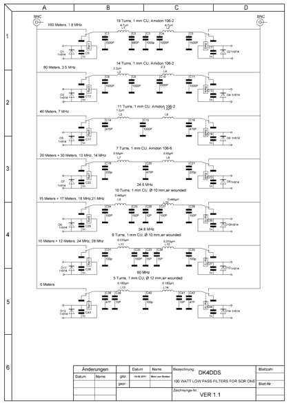
Circuit Diagram
Low Pass Filters for 100 Watt Mosfet PA |
|
Down
Load the Low Pass Filter Circuit Diagram in PDF Format |
|
Down Load the Bill
of Material for the SDR ONE Low Pass Filter Unit in PDF Format |
|
|
|
SMD Components
Placed and Soldered on to the Low Pass PCB Board |
|
|
| Down Load the Sprint Layout
Low Pass Filter File |
|
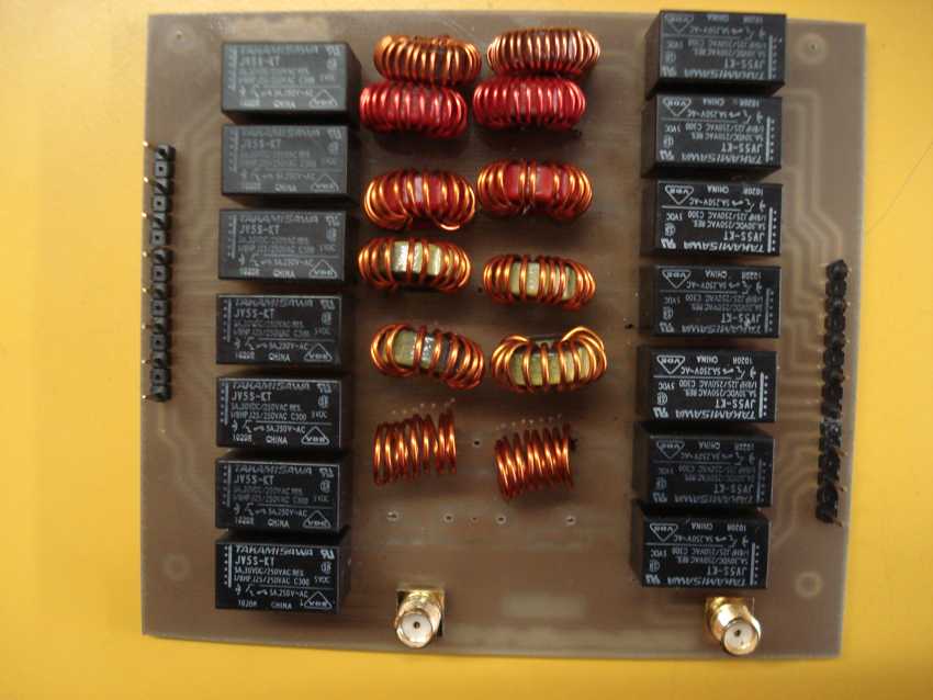
| Low Pass Filter
Unit Completed |
|
 |
|
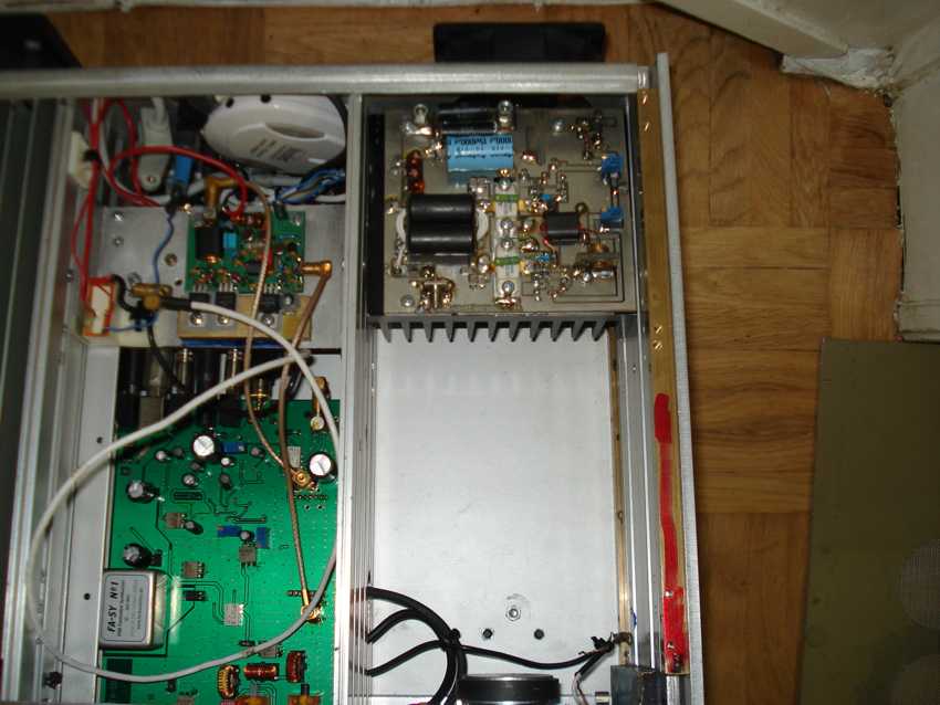
| 100 Watt PA Unit
mounted in to the 19 " Enclosure |
|
 |
|
|
| Low Pass Filter
Board into the Enclosure |
|
 |
|
| TiefPass-Leiterplatte
moniert im Gehaüse |
|
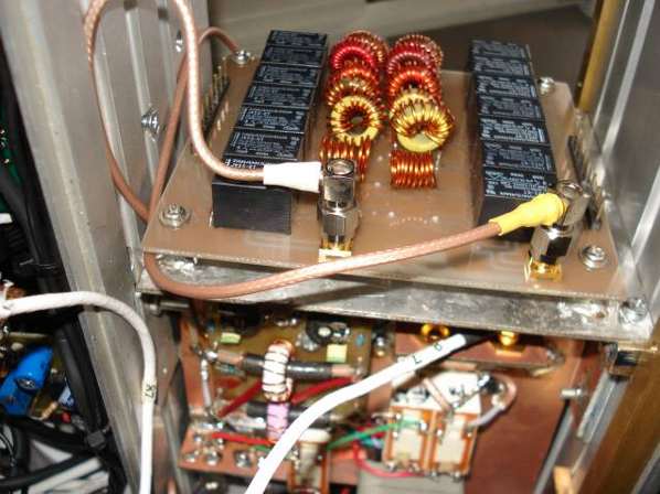
| Antenna Switch
Antenna, Antenna Relay Board & Power Measuring Module installed into the Transceiver |
|
 |
|
| Antenne-Umschalter,
Antennerelaisplatine und Leistungsmessung-Module eingebaut im Transceiver |
|
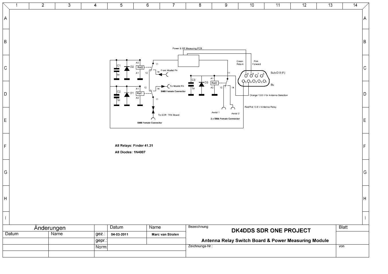
| Circuit Diagram
Antenna Switch & Antenna Relay Board |
|
|
|
| Schaltbild
Antenne-Umschalter und Sende / Empfangschaltung |
|
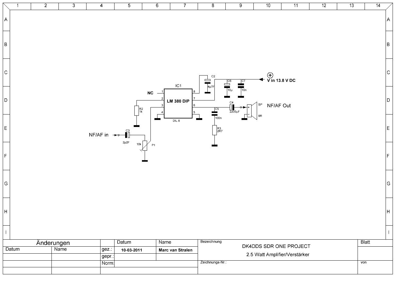
| Circuit Diagram of
the receiver AF Amplifier which mounted into the transceiver eclosure including a loud
speaker at the front |
|
 |
|
|