DOUBLE BOOM YAGI ANTENNA FOR 144 MHz DUBUS 4/2008
Slobodan Bukvić, YU7XL, yu7xl@nadlanu.com, http://www.qslnet.de/member/yu7xl/
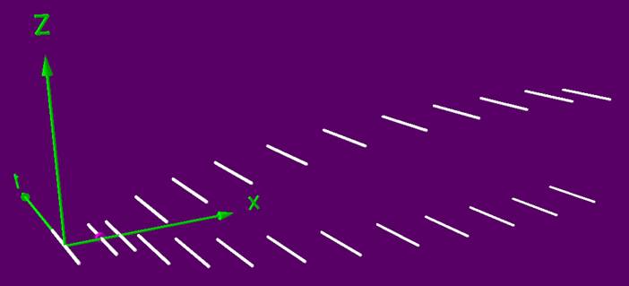
The antenna configuration presented here consists of two yagis stacked vertically a small distance apart.
Fig. 1
It has several advantages:
As seen from the Figure 1, the booms are not straight along. They are slightly bent toward each other at the directors end. One can find it not suitable for good reproduction, but the error in the vertical distance between the pair of elements is quite uncritical. The booms can easily be shaped on the vertical mast, and, at the directors end, by a piece of thin aluminum tube or by rope.
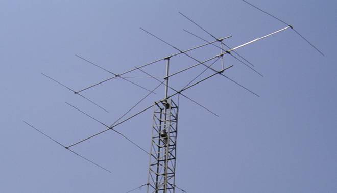
Fig. 2: Double Boom Yagi for 6m at YU7XL
As seen from the figure 1, the booms are not straight. They are slightly bent toward each other at the director end. One may find it not easy to reproduce accurately, but the error in the vertical distance between the pair of elements is quite uncrtical! The boom can easily be shaped when on the vertical mast bt a oiece of thin aluminium tube or by a rope at the directory end
During 2006/2007, I was using such a design for 50 MHz. It had 10 elements, the boom was approx 7 metres long and the calculated gain around 14 dBi. Figure 2 shows it. Actually, I was not quite satisfied with it because its first two directors were used just to obtain 50 Ohms impedance, adding practicaly nothing to the total antenna gain. So I put it down and searched for a better design.
ANTENNA X223A1XL for 2m
The antenna consists of one reflector, one radiator and 21 directors. Its boom length is 8 metres, exactly 799 centimetres. The maximum vertical height, the distance between the next to last pair of directors is 172 centimetres. The elements are mounted in a conventional way, and a boom correction is not applied.
Performance:
|
CONDITION |
G (dBi) |
F/B (dB) |
F/Sh (dBi) |
F/Sv (dBi) |
Hor (◦) |
Ver (◦) |
Temp (◦K) |
G/T (dB) |
ΔF * (kHz) |
|
No Loss |
17,29 |
28,86 |
25,05 |
17,67 |
29,4 |
25,0 |
219,0 |
-6,11 |
1150 |
|
Losses Included (Al) |
17,19 |
29,04 |
25,01 |
17,66 |
29,4 |
25,0 |
220,9 |
-6,25 |
Table 1
Dimensions:
|
|
Ref |
De |
D1 |
D2-3 |
D4-5 |
D6-7 |
D8-9 |
D10-11 |
D12-13 |
D14-15 |
D16-17 |
D18-19 |
D20-21 |
|
Pos |
0 |
398 |
601 |
969 |
1435 |
1986 |
2705 |
3535 |
4478 |
5367 |
6250 |
7155 |
7990 |
|
Length |
1010 |
955 |
942 |
916 |
922 |
912 |
902 |
888 |
876 |
868 |
862 |
852 |
848 |
|
Height |
- |
- |
- |
480 |
760 |
1000 |
1220 |
1420 |
1560 |
1660 |
1690 |
1720 |
1600 |
Table 2
REMARKS: - All elements made of Al rods Ǿ5 mm
- All dimensions given in milimetres
- The height stands for the distance between upper and lower elements
- Boom correction not taken into account
Comparison:
The following comparison table shows that the described antenna is better for approximately 20 to 25% than the same boom length single yagi antenna
|
Antenna |
Boomlength (mm) |
Material |
Gain (dBi) |
TA (◦K) |
G/T (dB) |
Bandwidth (MHz) |
|
X223A1XL |
7990 |
No loss |
17,29 |
219,0 |
-6,11 |
143,850-145,000 |
|
Aluminum |
17,19 |
220,0 |
-6,25 |
|||
|
EF0213-05 |
8150 |
No loss |
16,40 |
224,8 |
-7,12 |
143,660-144,620 |
|
Aluminum |
16,25 |
227,6 |
-7,32 |
|||
|
EF0215-5 |
10060 |
No loss |
17,27 |
223,0 |
-6,22 |
143,750-144,460 |
|
Aluminum |
17,06 |
226,7 |
-6,49 |
Table 3
Diagrams
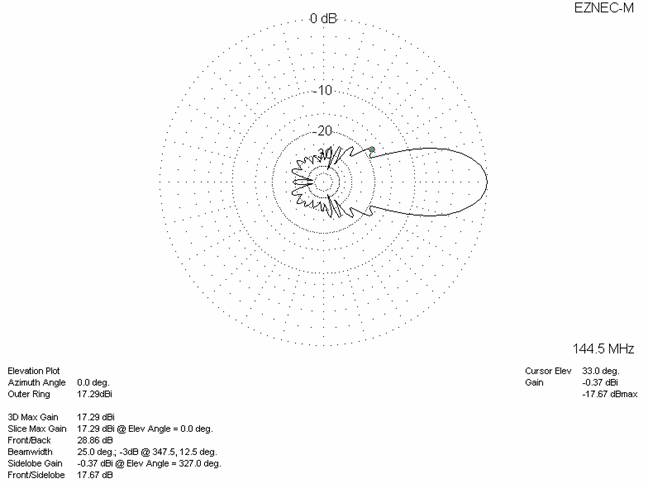
The following pages show the patterns for azimuth and elevation for a lossless condition (figure 3) with losses included (figure 4). Figure 5 shows the SWR sweep. Note: All simulation is with EZNEC!
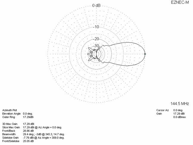
Fig. 3 Pattern – no losses included
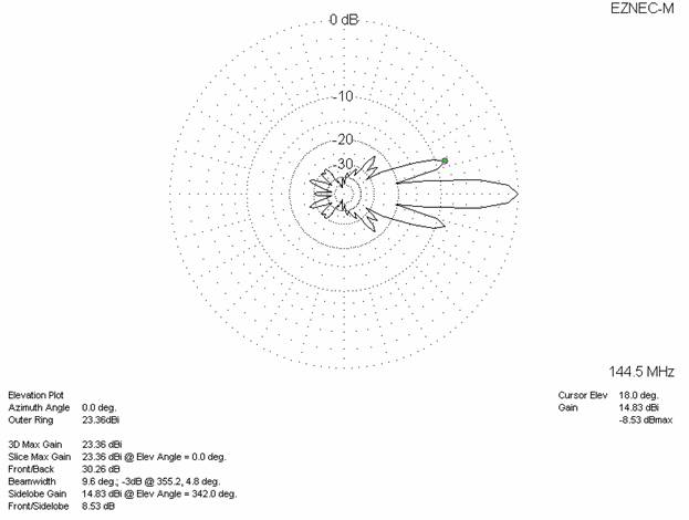
Diagrams (losses included)

Fig.4: Pattern – losses included
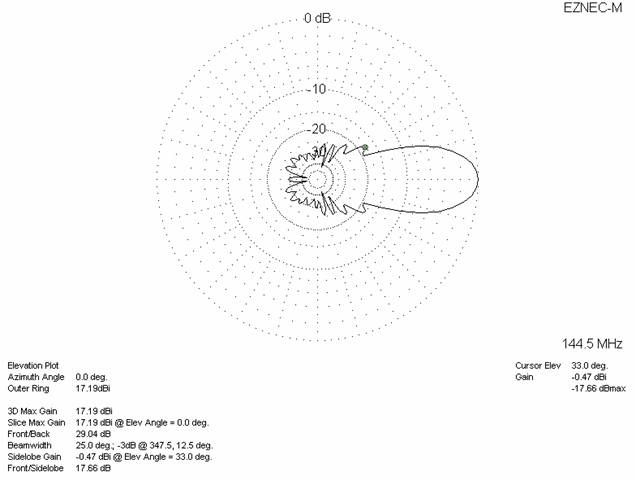
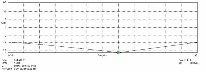
Fig. 5: SWR sweep
FOUR STACKED DOUBLE BOOM YAGIS
The double boom yagi antenna has a rather low temperature. Especialy in the vertical plane, the side lobe suppresion is fine and this allows high stacking up to 550 cm where gain and G/T stop increasing. The maximum distance in horizontal plane is lower – up to 470 cm. The following simulation is given for the stacking distance 460 cm horizontaly and 540 cm verticaly, see fig.6.
Within this stacking you will see an interesting thing: the gain for four antennas is higher than 6 dB!
No, nothing in the perpetuum mobile style, the explanation is simple: The area of highest gain is usualy at higher frequencies than the resonant frequency. When stacked, this area shifts down for some 200 kHz. Of course, the resonant frequency also shifts downwards; that is why I am using 144,500 MHz as a central design frequency.
Achieved performances: G=23,36 dBi TA=215,2 K G/T=+0,03 dB for no loss condition, and G=23,26 dBi TA=217,3 K G/T=-0,11 dB for loss included condition (aluminum rods Ø5 mm), see fig. 7.
A lower stacking distance – 400 cm horizontally and 480 cm vertically may also be tried. In that case, side lobe suppression would be 11 dB in both planes.
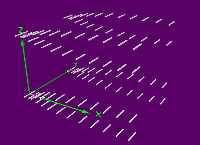
Fig. 6
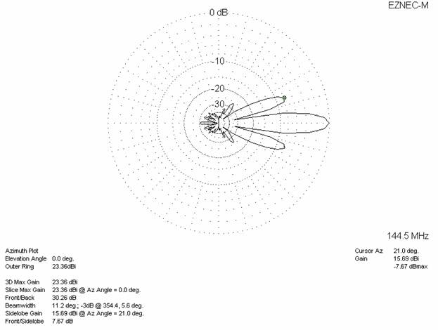
Fig. 7: 4 antennas – losses included, stacking distance H=460 cm, V=540 cm