Tech Note 1 Troubleshooting the ICF-6800W (WA) PLL
(last rev September 2009)
Note:
the problems of the ICF-6800W PLL mainly apply to the W version with
white model lettering on the front. The WA model (serial > 30.000)
has orange model lettering. If you have an orange version it is most
likely "just" an alignment issue. If you have a white one chances are
high you have a real problem. If you don't intend to dive in deep,
stay away from the white W version.
1. PREAMBLE
So... you could not resist and picked up this nice (or scruffy)
ICF-6800W... Chances are high it doesn't work on shortwave bands....
The 6800W is a synthesized unit, with a phase locked loop transferring
frequency stability of a crystal to the LO (VCO1 in this case). Now
these days PLLs are a piece of cake taking a few 10s of MHz reference
and a VCO at frequencies up to GHZ directly. One programs the
comparison frequency and dividing numbers and out comes the correction
signal, you only have to supply the loop filter. Not so on the 6800W...
this one use a nice discrete approach for most of the RF pieces of the
PLL to get down to a low comparison frequency. The 6800
incorporates aspects of the Wadley loop but, imho, it is not a
traditonal application thereof. Yes, one selects a harmonic of a
reference to mix down, but not in the signal path, only in the VCO - so
the triple conversion is avoided.
Enough said... all you are interested in is to get it going again. So, let me ask whether:
You have a lot of time to waste.
You have decent mechanics skills and close-by eyesight.
You have good electronics skills, HF centric.
You like to go to bed with schematics and service manual (SM) instead of whiskey.
You have access to some test equipment.
You really really want to get it working again.
If the answer to all
the above is yes, please read on. If not, please put the unit back on
Ebay. There's always a fellow soul who has not read this yet who's
willing to pick it up - with today's prices on 6800W's you may even
make a decent profit - doesn't that look a LOT better suddenly? If you
take a shot at it but can't get it to work, reassamble correctly and
have the decency to tell potential buyers what you did.
2. WHAT'S GOING ON IN MY 6800 LOOP?
Here's a basic flowchart I use to fix (working under the assumption
that all else is sort of fine) - spend a few hours on the
schematic/explanation of the service manual first so that you
understand all circuit principles and how the building blocks relate:
a. The counter doesn't work: not good, you will need it. Check the 10MHz reference, and the divider on the counter board.
b. MW doesnt work: there is no readout on MW and no reception. You need
to fix this first. The VFO around Q22 used on MW also feeds directly into the
phase comparator IC3. Look into the MW board and the counter buffers
Q25/26.
c. SW: the counter shows a number like 89300 or so... VCO1 is not
oscillating (most likely) or the counter buffer is gone. Check/clean
switches and the capacitor switch. Maybe it is really out of alignment.
d. SW: in the most common problem scenario you will see a number that
is a bit higher than the band you are on. For example when on 0/3MHz
(=3-4 MHz) the number 4325 is on display, and it does not move a you
spin the dial. The good news is VCO1 is working - the bad news is it is
running unlocked. Many, but not an unlimited, number of causes
are possible:
- VCO2 does not work (usually misaligned)
- the FET mixer Q31 does not work (not very likely)
- the 10MHz amplifier Q32 does not work (mmm, sometimes is weak, but it
should not be top problem, look into this if 10/ range works and 0/ 20/
don't)
- the output of the FET mixer and 10MHz are mixed together in
Q33 (a likely source of problems). This one has to work good, or
you will not have enough drive for the filter and the subsequent
squarer/divider.
- one of the various buffer stages has degraded.
So all in all, not so easy to tell what's going on. It usually is one
of the 2SC930 transistors failing. In fact, most of them are below spec
after these years on the W version. But since we clean up everything in
the squarer some
loss of signal is not too bad - we just need "enough" at the end,
and can tolerate quite a lot. That is why Q32/33/34/35 are critical. So
I don't believe in ripping out all the 2SC930s... You just have to find
the key one(s). Replace with, for example, BF241 or new 2SC930. Also
investigate Q23 on the MW board if you have weak MW reception and/or
consistent partial lock (e.g. XY200-XY500 kHz) regardless of X/Y
setting.
3. DIAGNOSING THE PATIENT
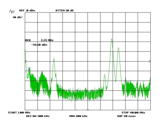
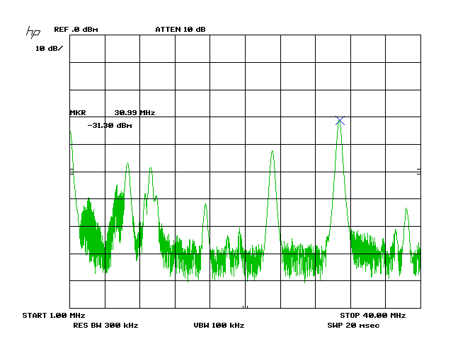
Find the Q31 FET, next to it sits C113. A long leg is exposed, and you don't have to do further disassembly once the case is off.
Here you can see a lot of interesting stuff. You will load the FET with
the 50 ohms of your analyzer causing the voltage to collapse so the PLL
will go out of lock - no problem... That is not relevant here.
Also the absolute power measurements are hard to relate to
the scope Vpp's of the schematics because of different impedances etc.

This picture show the 1/0 =(10 MHz) setting. One can see all relevant
signals: The 28MHz VCO2, the 30MHz VCO1, and the 2MHz difference. The
10MHz is visible, but remember 10MHz mixing stage is not used in the 1/
range.

This picture show the
0/3
=(3 MHz) setting. One can see all relevant signals: The 31MHz VCO2,
the 23.5MHz VCO1, and the 7.5MHz difference. The 10MHz mixing stage is
used. The 10-7.5=2.5MHz is hard to see in this measurement.

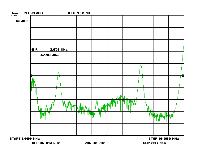
... but you can see it really well at the output of Q33. 10MHz, 7.5MHz
and the difference. It is this difference signal that goes into the
Q34/35 amp and then into the squarer.
So looking at the FET really gives you a lot of info. Do the VCOs work,
is VCO2 locked (you ll see it jump if not because of the sweep circuit)
and on the right harmonic, and do the mixers work. That's basically the
whole PLL. The chance something is wrong with the
squarer/divider/comparator chain is low. You may want to check the Cs
in the loop filter, but in the 80ies, Sony components used were in
general good quality.
Looking at the input pins of the squarer IC3 also gives a good estimate
of signal quality - compare the usually clean VFO (if Q23 is ok) with
the signal out
of the low pass filter/buffer. Note the importance of Q35/36 for
setting Vavg on the squarer/divider - if Vpp is weak the DC bias
becomes important.
4. ALIGNMENT
Put all the compartment and PCB shields back in place. If not, you will not achieve lock on several frequencies.
a. First make a good VCO2 alignment
Follow the service manual procedure. A, B, C are around 3.25 2.32 4.25V.
Note error regarding adjustment locations in SM. The outputs from 28 to
37MHz in 1MHz steps should be rock solid. Confirm on FET
Q31 as above.
b. IFT 10MHz L25 adjustment, peak for maximum mixer product in the 0/ or 2/ range.
c. Then VCO1 alignment.
This one is a whole lot tricker. The better approach would be to
characterise the low and high frequency of VCO1 for each band setting
(29 in total) and check for anomalies first. The yellow wire at the
underside of the PCB has the VCO1 correction voltage. If you unsolder
it you can swing the VCO between min (Vcorr), about 0.8V and
max(Vcorr), about 4.7V. You can calculate the capture/lock range of the
VCO1 and attempt to adjust the VCO so that it covers the band as
intended whilst keeping the correction voltage away from 0.8V and 4.7V.
The
procedure in the service manual is a bit more ad hoc. It suggests a
setting of the max VCO frequency on each band at max(Vcorr), given
factory VCO behaviour. Not a problem as such, but a few considerations
need to be made:
i. the VCO behaviour changes because of aging.
ii.
you cannot change the 3 decades independently as presented in the SM.
CT8 is common to all decades. That's important: you can set up SW1-CT8
correctly and then take a shot at SW2-CT9/SW-3-CT10 never finding a
satisfactory setting for the latter. So the alignment process should be
iterative.
iii. the band switches and the switched capacitor bank need to be working fine or you will never get it completely right.
iv.
the tuning dial position is entirely irrelevant during adjustment. Once
you touch the CV1-11, you are basically destroying the VCO2 xMHz
signal, and the mixer side of the comparator input goes away. The VFO
input remains in place, and Vcorr will go max.
OK, let's proceed. YMMV, but this works for me.
Step
1. First check (iii), while disabling the PLL as indicated as one
swicthes between the 3 decades the difference x/9 - x/0 should be of
similar magnitude. If you have one that is 5 times the others, you
are probably losing Cgang in the swicthed capacitor. 0/0 is a bit of
an exception being a bit high than the others, say 1500 to 1900 kHz.
Adjust incorrect Cgang by adding/removing C on the switched capacitor.
Step
2. Set x/9-x/0 to be about 9 to 10 MHz. Again, because of 0/0
being a bit higher 0/0-0/9 will be more like 8.5-9Mhz. For this
adjustment, use CT8.
Step 3. Align SW2, using L33/CT10. Try not to change CT8.
Step 4. Align SW3, using L32/CT9. Try not to change CT8.
Step 5. Adjust SW1 using L34.
Step
6. Recheck Step 2 if you find higher MHz of a decade not locking. To
check this capture first at low end of MHz using dial, then move up.
You
should end up after a while with a PLL remaining in lock everywhere,
even though it may not capture everywhere immediately upon each switch.
I think that's normal to some extent after 30 years and the discrete
swicthing.
I
like the loop to be tight, and use these numbers as guidelines. Service
manual values between brackets. This gives an idea how the numbers can
vary.
| kHz |
0/ |
1/ |
2/ |
| /0 |
2000 (2145) |
11200 (11745) |
21200 (21745) |
| /1 |
2750 |
12275 |
22325 |
| /5 |
6400 |
16750 |
26600 |
| /9 |
10500 (11045) |
21200 (20745) |
30750 (30645) |
By now, the PLL should be stable... and one can get to the rest of the alignment of the radio... a lot easier.
5. DOCUMENTATION
One can find decent scans of the service manual on the web (Mauritron
original). It is good quality except for the PCB layouts... this could
be better. Anyone have a better source or pdf?
back


