ROVERBOX - Xlock-1g
1GHz DDS reference clock
ON4IY and ON4CDU -- January 2010
0. Xlock-1g?
We designed the Xlock based on the
LMX23x6 a few years ago with good results for xtal VCO locking.
Experiments with the original Xlock board showed limitations for
locking a Crystel VCO at 1 GHz. The PLL chips are too noisy. So we
decided to move to the largely pin-compatible ADF4106/7. This page
describes the differences with the original Xlock design. Xlock-1g uses
the same PCB as the original Xlock.
1. Project status
- Finished, docs and measurements done.
2. Prototype testing and initial units: results
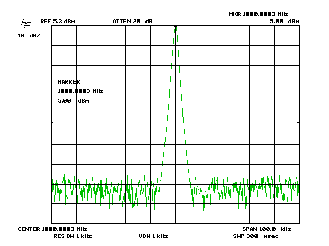
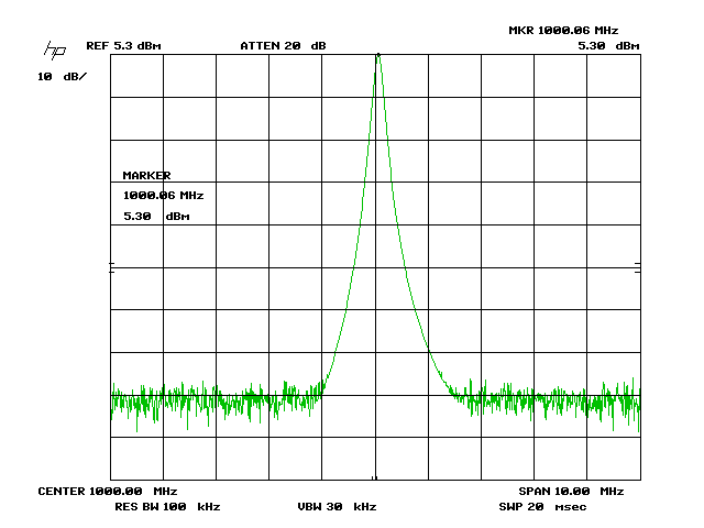
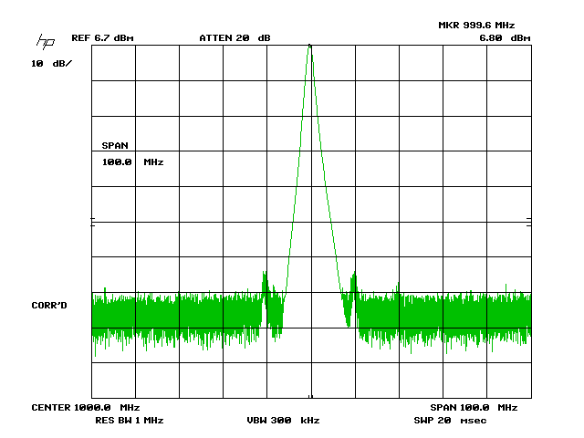
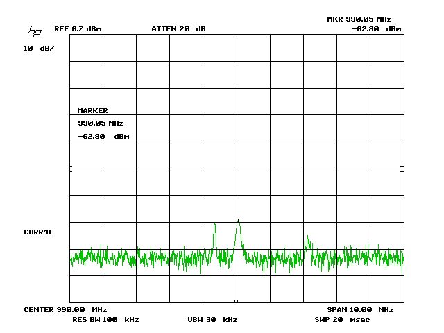
The output is clean: intermod at 990/1010MHz is 70dB down - no other products noticed.
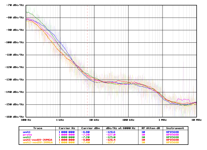
Note -108dBc @ 1kHz offset in production units
3. Differences with the Xlock
The changes are mostly the result of the ADF taking a different supply
voltage. It also has a different reference input: digital versus RF on
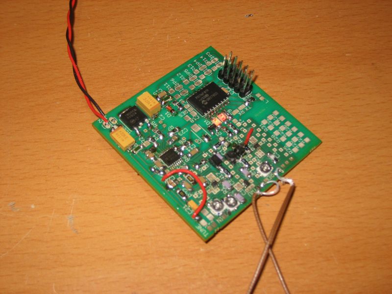
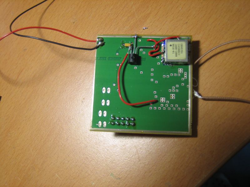
the LMX. Mounting style as depicted in the pictures above.
- The input capacitor to the LMX of 470pF is replaced by 1nF/47R to ground/1nF
- An 1.5K resistor from the pad at pin 1 to ground
- The Crystek CRO is mounted on the underside of the board so that its output pin is just under the input pin of the PCB.
- A LP2950 3V regulator is mounted on the underside of the board - input at 5V rail
- From the regulator output
- To power supply of ADF (DELETE R2)
- To minimise intermod, the 10MHz MMIC needs to get a supply
different from the other MMICs. Put the L on its side, and connect to
the 3V of the LP2950
- Loop filter:
- 150Hz at 125uA Ip
- C1 200nF, C2 3.3uF, R1 1,5K
4. Alignment
A bit of alignment is needed to get best phase noise and minimum intermod between 1GHz and 10Mhz.
Align the variable resistor at the 10MHz ref input as follows:
- at input +7dBm, align for ref input to the ADF 1.6Vpp, phase
noise will be as measurede above and intermod 70db below 1GHz carrier
- at input -3dBm, align for ref input to the ADF 1.2Vp, phase noise will
be as measurede above and intermod 75db below 1GHz carrier
5. CCS Code
x1gadf.h
#include "/home/xtof/sun/ccs/devices/16f819.h"
#FUSES
NOWDT
//No Watch Dog Timer
#FUSES
INTRC_IO
//Internal RC Osc, no CLKOUT
#FUSES
PUT
//Power Up Timer
#FUSES
NOPROTECT
//Code not protected from reading
#FUSES
BROWNOUT
//Reset when brownout detected
#FUSES
MCLR
//Master Clear pin enabled
#FUSES
NOLVP
//No low voltage prgming, B3(PIC16) or B5(PIC18)
used for I/O
#FUSES
NOCPD
//No EE protection
#use delay(clock=8000000)
#use rs232(baud=9600,parity=N,xmit=PIN_B2,rcv=PIN_B1,bits=8)
#define LMX_LE PIN_A0
#define LMX_DA PIN_A1
#define LMX_CL PIN_A2
#define GREEN PIN_A3
#define RED PIN_A4
#define LOCK PIN_B3
#define JMP2 PIN_A6
#define JMP3 PIN_A7
#define LMX_LD PIN_B0
#define RX PIN_B1
#define TX PIN_B2
#define SPARE PIN_B3
#define JMP0 PIN_B4
#define JMP1 PIN_B5
#define GREEN_ON output_low(PIN_A3)
#define GREEN_OFF output_high(PIN_A3)
#define RED_ON output_low(PIN_A4)
#define RED_OFF output_high(PIN_A4)
#define LOCK_ON output_high(PIN_B3)
#define LOCK_OFF output_low(PIN_b3)
x1gadf.c
#include "x1gadf.h"
void
ADF_write_byte (unsigned char data, unsigned char number)
// write the the <number> of <data> to the lmx, msb first
{
while (number > 0) {
output_low(LMX_CL);
delay_us(1);
output_bit(LMX_DA, (data & 128));
delay_us(1);
output_high(LMX_CL);
delay_us(1);
output_low(LMX_CL);
data = data << 1;
number--;}
}
void
ADF_write (unsigned char data1, unsigned char data2, unsigned char data3)
// write the 21 MSBs
{
output_high(LMX_LE);
delay_us(1);
output_low(LMX_LE);
delay_us(1);
ADF_write_byte(data1, 8);
ADF_write_byte(data2, 8);
ADF_write_byte(data3, 8);
delay_us(1);
output_high(LMX_LE);
}
void
sayhi(void)
{
GREEN_OFF; delay_ms (100);
GREEN_ON; delay_ms (100);
}
void
blink (unsigned char number)
{
if (number == 0) {
RED_OFF; delay_ms (250);
RED_ON; delay_ms (750);
RED_OFF; delay_ms (250);
}
while (number > 0) {
RED_OFF; delay_ms (250);
RED_ON; delay_ms (250);
RED_OFF; delay_ms (250);
number--;}
}
void
main(void)
{
unsigned char jump;
setup_timer_0(RTCC_INTERNAL|RTCC_DIV_1);
setup_timer_1(T1_DISABLED);
setup_timer_2(T2_DISABLED,0,1);
setup_adc(ADC_OFF);
LOCK_OFF;
sayhi();
// OK, now everybody nows we are running, let s get going
blink(4);
// write N R F
// to LMX chip
ADF_write(0, 0, 150);
ADF_write(0, 0, 4);
ADF_write(0, 12,17);
ADF_write(0, 0, 146);
// I think we are done here, say goodbye
sayhi();
// for (;;) continue; // done. loop forever
while (1>0) {sayhi(); if (input(LMX_LD)) {LOCK_OFF;RED_OFF;} else
{LOCK_ON;RED_ON;}} // test always do something
}
x1gadf.HEX
Author: on4iy@qsl.net.
Version: Sat Jan 30 17:06:14 CET 2010
