|
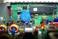
opened box with view of back of frontpanel,part of RF board and filterboard |
|
|
the backside of the frontpanel board,the big IC is the Micro Controller Unit |
|
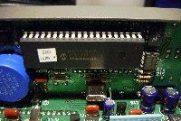
| closer look of the MCU | |
| part of the filter board | |
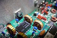
| part of the filter board with 4 toroids to wind | |
|
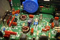
closer look to the toroids with the PA-transistor mounted to a side panel |
|
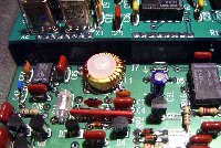
| the VFO toroid,the windings not evenly spaced,but had to spread a bit to meet the required frequency | |
| part of the RF board with the 4 Xtals on the side | |
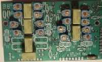
| picture of not finished KFL1-4, shows exactly the right order how to place the new blue trimmer-caps
|
|
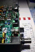
| the rear panel with antenna jack,ON/OFF switch,power connector and key jack |

